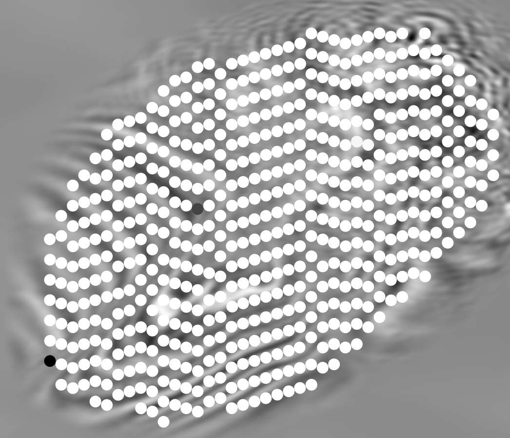
logo
Introducing TSL-FWI™

TSL-FWI

Time Space Lag — Full Waveform Inversion

TSL-FWI's matching filters operate across time and space — aligning seismic events across traces, defeating temporal and spatial cycle skipping, and recovering accurate macro-models from starting points conventional FWI can't survive.

Cycle-skipping robustReflection moveout sensitiveRTM-ready macro-models
Case study · The live build

Alaminos Canyon, step by step

This is a TSL live model build starting from almost nowhere - we will walk you through every step of the sequence with XWAI driving the decisions, the parameters, and the understanding along the way.

00M0 → M1Starting model

A compaction trend and a rough guess at the salt.

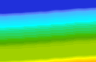
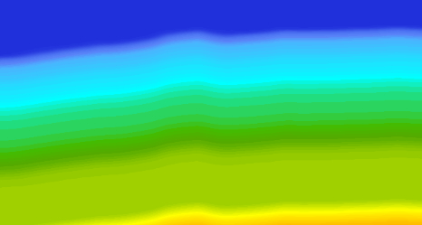
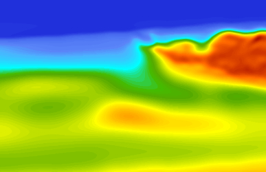
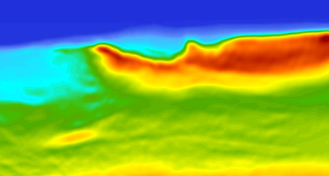
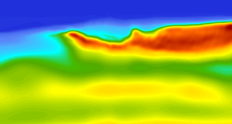
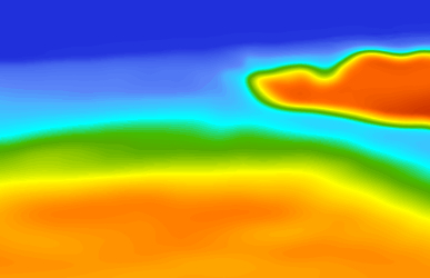
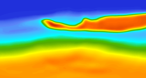
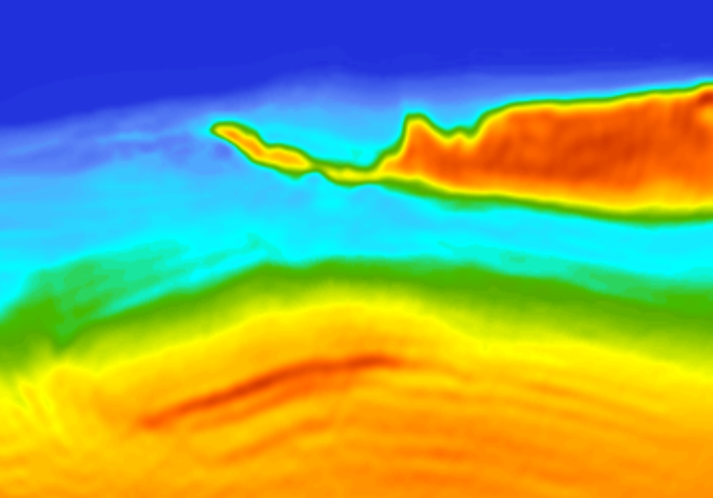
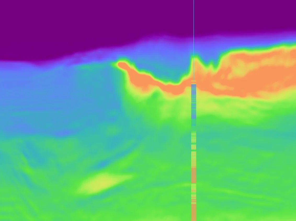
The build starts from almost nothing. M0 is a regional compaction trend — velocity simply increasing with depth. No structure, no salt, no local geology.

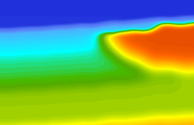
M1 adds the first, highly approximate salt geometry on top of that trend. That is the entire starting point for the inversion.

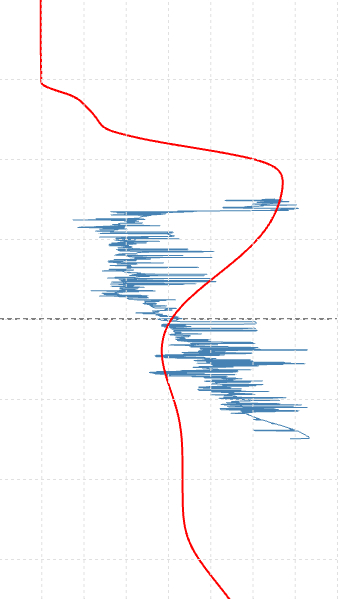
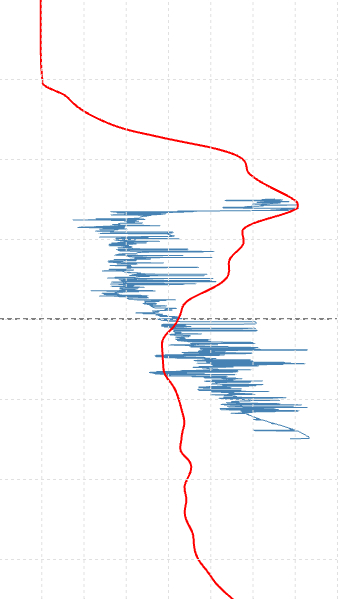
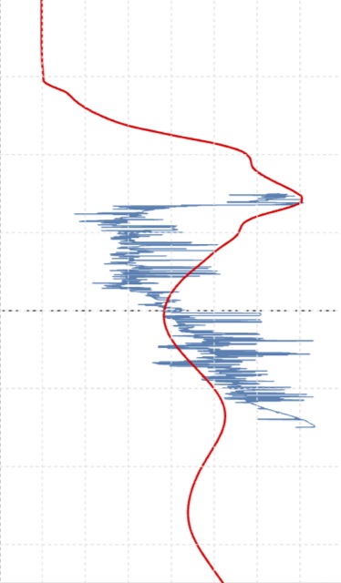
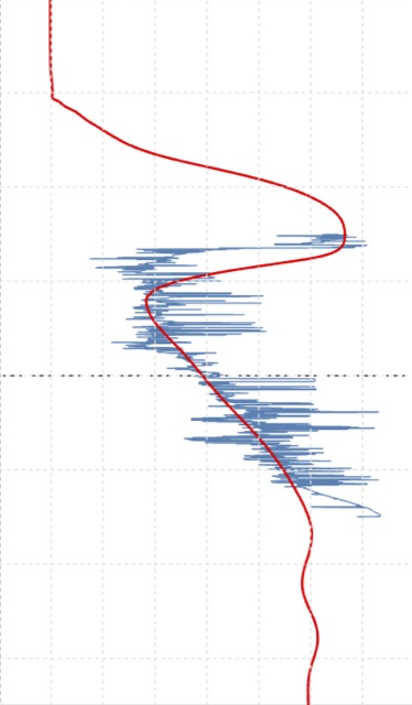
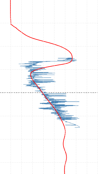
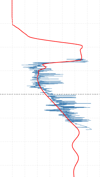
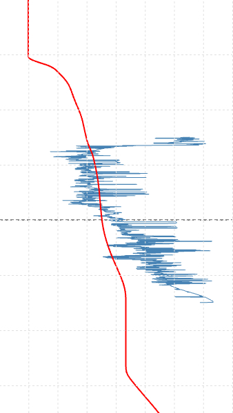
A blind sonic log — withheld from the model build — shows just how far this is from reality: overshoots and undershoots of more than 1,000 m/s between the initial model and the true earth.

Errors of this size are exactly where velocity model building breaks down. Conventional workflows can correct them, but slowly and manually. Feed M1 into standard FWI and cycle skipping destroys the inversion instantly. This is the regime the rest of this build is designed to survive.

Driven through XWAI
  • Instant tracking and summarising of starting jobs in FWI flow
  • Live rendering of before and after M0 model sections at IL 552
  • Expiration of physics-based top salt update — answered from the knowledge base
XWAI — Copilot2.0Live
A real XWAI session on M0 → M1, replayed message by message.
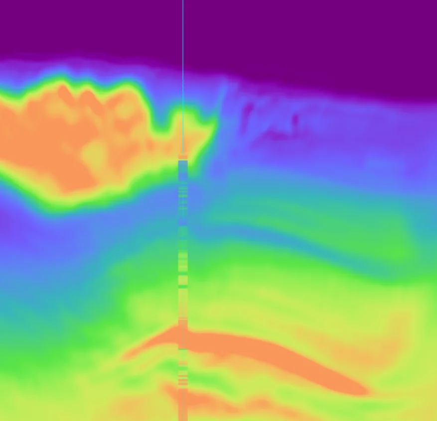
Blind sonic log against the M0 and M1 model profiles at the well — M0, Blind wellBlind well
Click to flip
Model Vp (red) against the blind sonic log (blue) — overshoot and undershoot beyond 1,000 m/s.
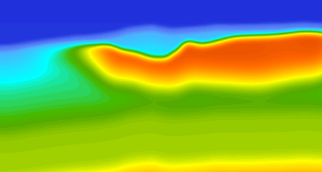
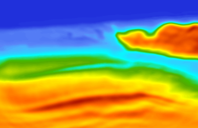
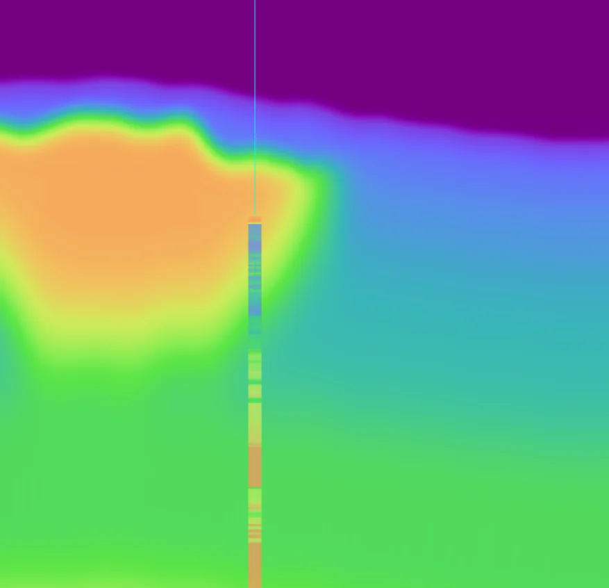
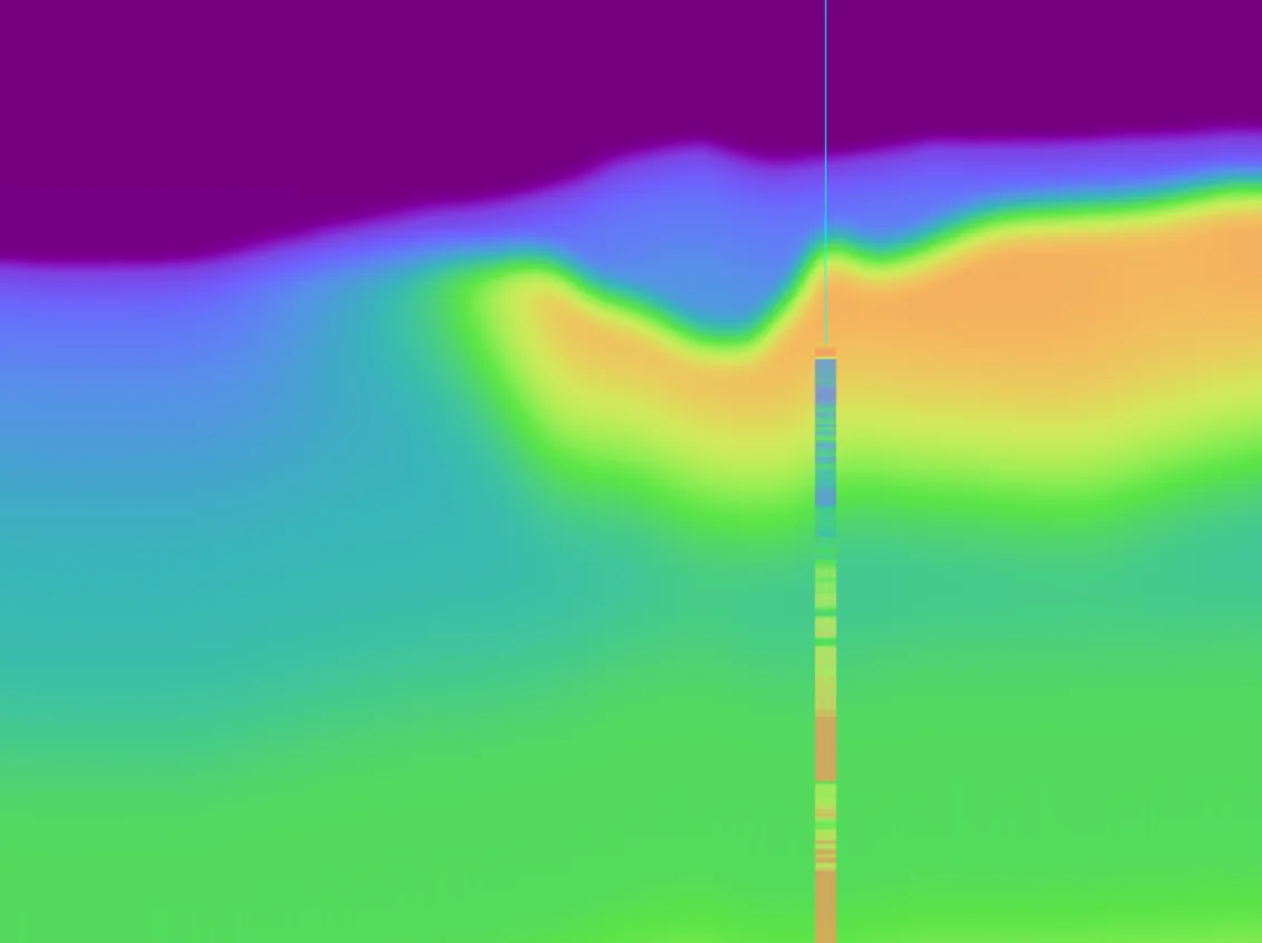
M0 to M1 — regional compaction trend to approximate salt geometry — M0, Inline 552Inline 552
M0 to M1 — regional compaction trend to approximate salt geometry — M0, Crossline 414Crossline 414
Click to flip
Inline 552 and crossline 414 Vp sections.
01M1 → M2FWITSL-FWI

One update, acting on every level at once.

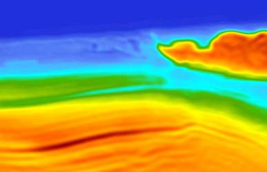
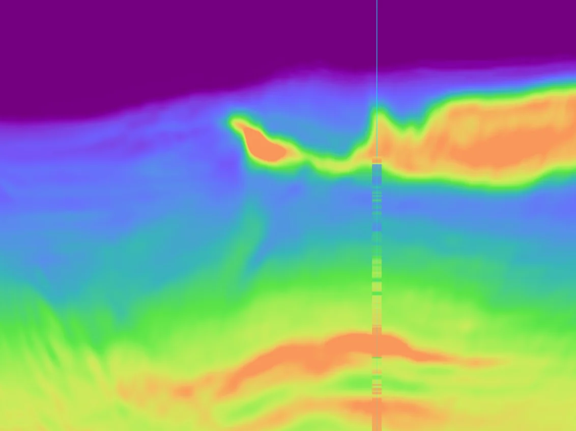
M2 is where TSL goes to work. TSL generates an FDR (FWI-Derived Reflectivity), and the update acts simultaneously across multiple levels of the model — no staged, layer-by-layer intervention required.

In the upper part of the model, TSL acts to define the salt geometry — carving structure out of what was only a rough guess at the start.

Below, it recognises the velocity is too high and acts to reduce it sharply — bringing the model back in line with what the sonic (used here only to test) shows to be true.

Two very different corrections — defining geometry above, reducing velocity below — delivered by a single update. This is what the extended Time-Space-Lag objective makes possible.

Driven through XWAI
  • Instant summary of job sequences
  • Diagnostic of stalling jobs - the AI model utilises vast technical documentation to give informed technical responses
  • Crossline slices of all three rendered in the thread for job comparisons
XWAI — Copilot2.0Live
The M2 FDR session — every visual rendered live in the thread.
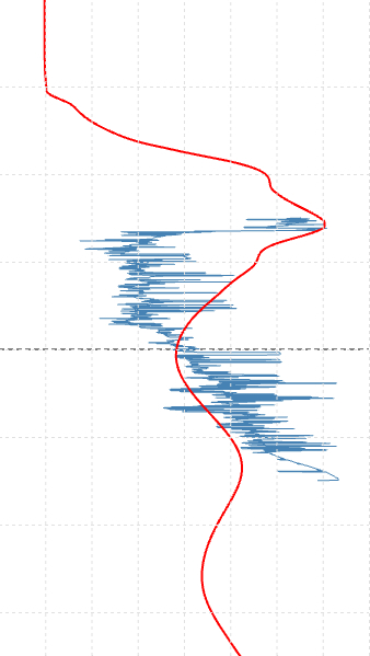
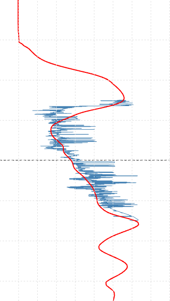
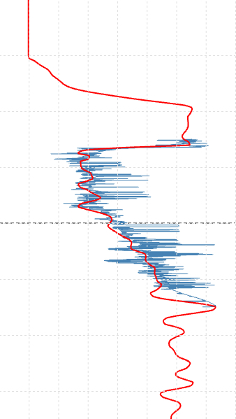
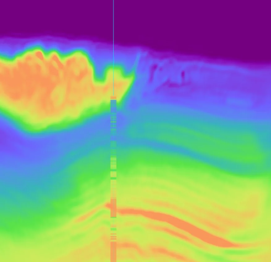
Blind sonic log against the M1 and M2 model profiles at the well — M1, Blind wellBlind well
Click to cycle
At the well — below the log the update pulls the overshoot velocity sharply down toward the sonic.
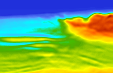
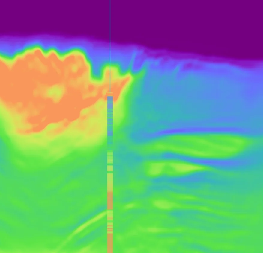
M1 to M2 — the first TSL-FWI update acting across the model — M1, Inline 552Inline 552
M1 to M2 — the first TSL-FWI update acting across the model — M1, Crossline 414Crossline 414
Click to cycle
Comparing salt geometry models after using FWI and TSL
02M1 → M3TSL-FWI

The errors reverse — and the model converges.

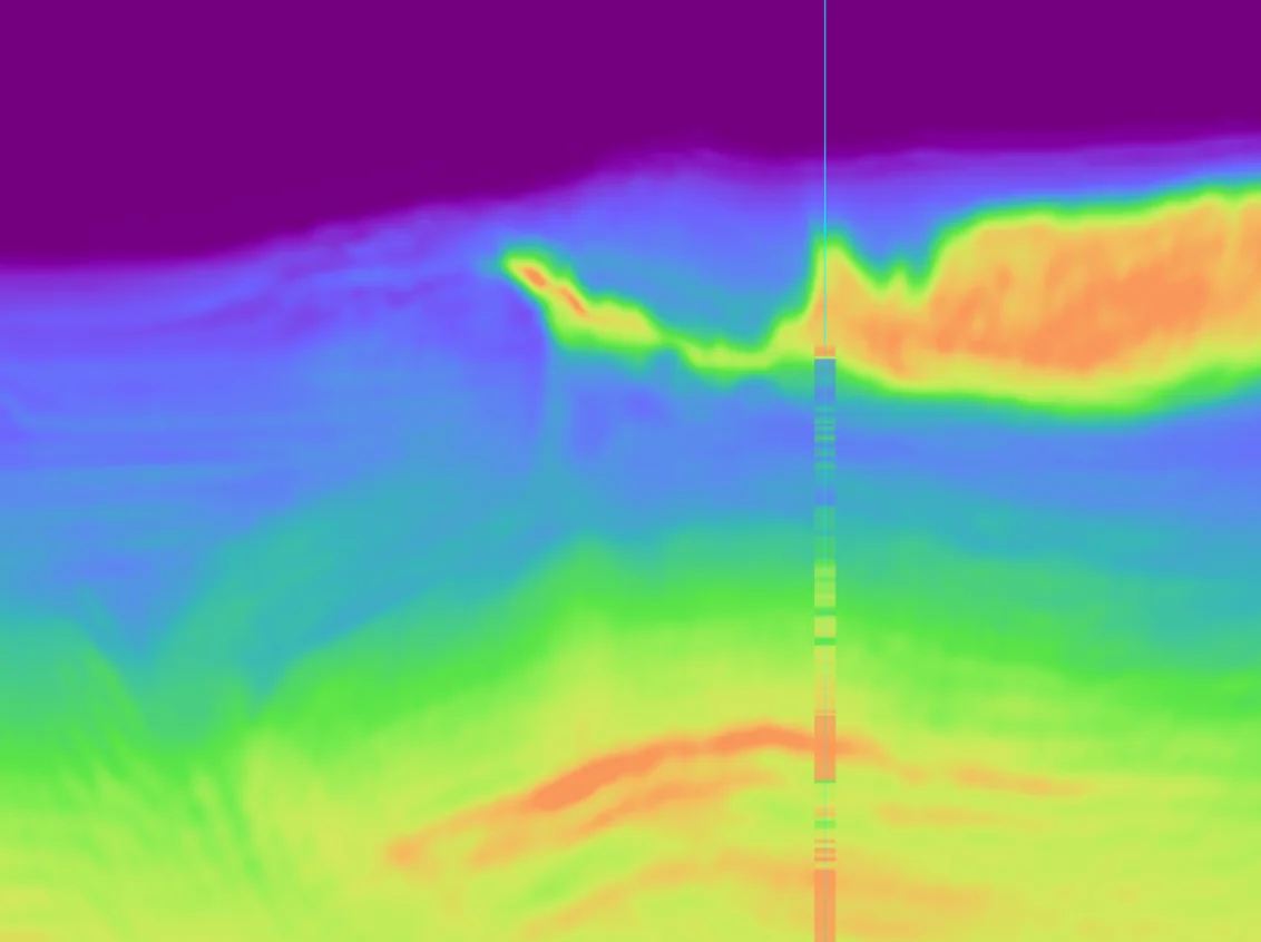
M2 lands after a round of merged updates, and this is where it turns: TSL reverses the errors and the inversion converges.

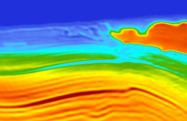
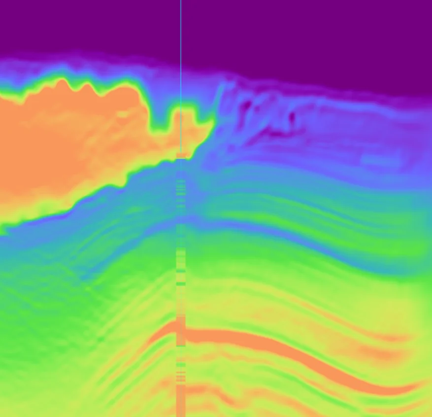
The base of salt is pulled up towards its correct structural position.

Deeper down, the velocity approaches the sonic trend — the 1,000 m/s-plus misfits from the starting model collapsing onto the blind log.

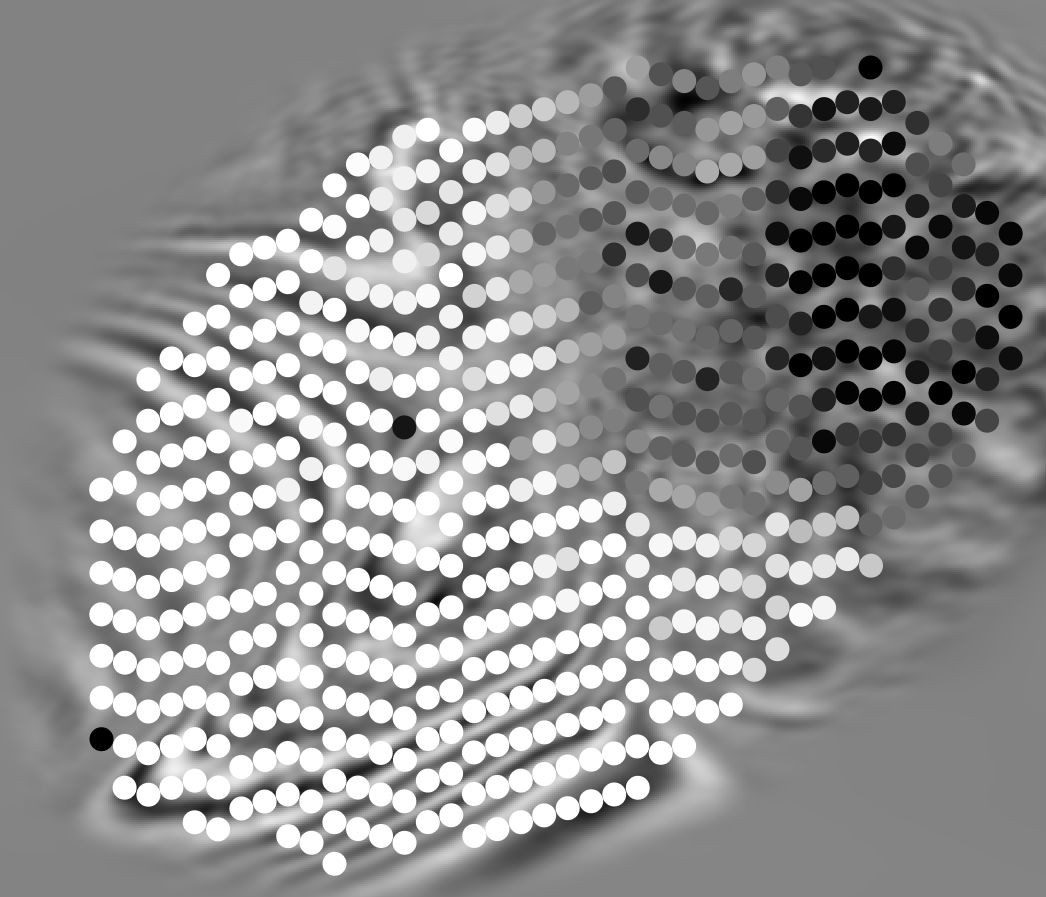
And it isn't just right at the well. FDR metrics validate the update spatially, across the survey, far beyond our isolated well location.

Driven through XWAI
  • The ALM-50m processing stages laid out in one answer
  • The M1 → M3 progression, and its challenges, explained
  • FDR metric analysis across all shot
  • Comprehensive review of FDR imaging
XWAI — Copilot2.0Live
The M1 → M3 session, replayed from the project record.
Blind sonic log against the M2 and M2 model profiles at the well — M1, Blind wellBlind well
Click to flip
At the well — the deep velocity converges onto the sonic trend.
M1 → M3 — merged updates converging, base of salt pulled up — M1, Inline 552Inline 552
M1 → M3 — merged updates converging, base of salt pulled up — M1, Crossline 414Crossline 414
Click to flip
Base of salt pulled up, deep velocity onto the sonic trend.
Depth slice at 100 with per-shot trace-fit overlay — M2 FDR against T1 — M1-FDR, Depth 100 · shotsDepth 100 · shots
Click to flip
FDR metrics across the survey — per-shot fits overlaid on the depth slice validate the update far beyond the well. Each point represents a shot - lighter is better.
03M3 → T1TSL-FWITargeted

Going after the salt, target by target.

With the macro model converged, TSL switches focus to sharpening the salt further.

The FDR metrics are happy — except at the salt extremity. There we run into an overshoot artefact: high salt velocities bleeding into the adjacent sediment.

That kind of localised defect doesn't need another survey-wide pass. It needs precision.

So the build changes gear from M to T — Targeted. From here on, the updates go after very specific parts of the salt, and nothing else.

Driven through XWAI
  • A003-TSL and A004-FWI compared on convergence and parameters in one ask
  • Crossline 414 rendered live for both candidates
  • The lineage from checkpoint 30 traced to find the branch that carried the build
  • A006-TSL and A007-TSL examined to set up the next targeted move
XWAI — Copilot2.0Live
The T1 session — choosing the branch that carries the build forward.
Blind sonic log against the M3 and T1 model profiles at the well — M3, Blind wellBlind well
Click to flip
At the well — the profile holds the sonic trend while the salt sharpens.
M3 to T1 — salt sharpened, overshoot artefact appearing at the salt extremity — M3, Inline 552Inline 552
M3 to T1 — salt sharpened, overshoot artefact appearing at the salt extremity — M3, Crossline 414Crossline 414
Click to flip
M2 → T1 — the salt sharpens; note the overshoot at the salt extremity.
04T1 → T2TSL-FWIParameter scan

A parameter scan cracks the salt extremity.

The salt extremity is tackled through a parameter scan — and T1 is the update that wins it.

The overshoot is corrected, and the deeper imaging distortions it was causing are eliminated with it.

With the artefact gone, deeper sedimentary layers emerge from beneath the salt.

But the build isn't finished: under the salt, a loss of continuity remains…

Driven through XWAI
  • A003-TSL's checkpoint-40 experiments listed with their final trace-fits
  • The top four jobs ranked, functionals and iterations identified
  • Each branch explained in context from the parent's comments
  • The tile-traces × AWI-scale grid search designed and drafted in chat
XWAI — Copilot2.0Live
The T1 → T2 session — the parameter scan, designed in chat.
T1 to T2 — overshoot at the salt extremity corrected by the parameter scan — T1, Inline 552Inline 552
T1 to T2 — overshoot at the salt extremity corrected by the parameter scan — T1, Crossline 414Crossline 414
Click to flip
T1 → T2 — the overshoot corrected, deeper sedimentary layers emerging.
05T2 → T3TSL-FWI

Going deeper and fixing anomalies.

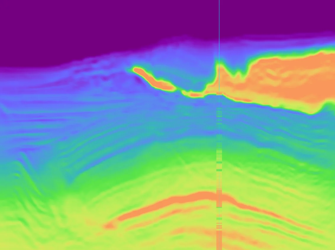
T2-FWI checks the model and the deeper sediment layers finally emerge — but continuity is lost in the reflectors under the salt.

The fix is a merge: T2-FWI's smooth sediment fused with a sharper salt geometry, giving TSL a clean starting point.

A 22-step AWI/RWI sequence refines it further, closing in on the sub-salt zone with masking and rising frequencies.

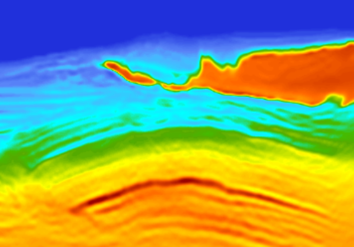
The result is T3 — continuity restored under the salt, and the velocity range widens to reveal deep, compacted sediment.

Driven through XWAI
  • A004-FWI to A011-TSL lineage traced across the full AWI/RWI sequence
  • The salt-and-sediment merge behind A008-TSL explained
  • A004-FWI and A011-TSL parameters compared side by side
  • Crossline 414 rendered live for all three stages
XWAI — Copilot2.0Live
The T2 → T3 session
T2 to T3 — T2, Inline 552Inline 552
T2 to T3 — T2, Crossline 414Crossline 414
Click to flip
T2 → T3 - continuity restored under the salt
Loading the full session…

See it work on your data.

Open the live preview and put XWAI to work the way you just watched — or talk to us about running a TSL-FWI build on your own project.

Free preview · takes 20 seconds to start